Glossary
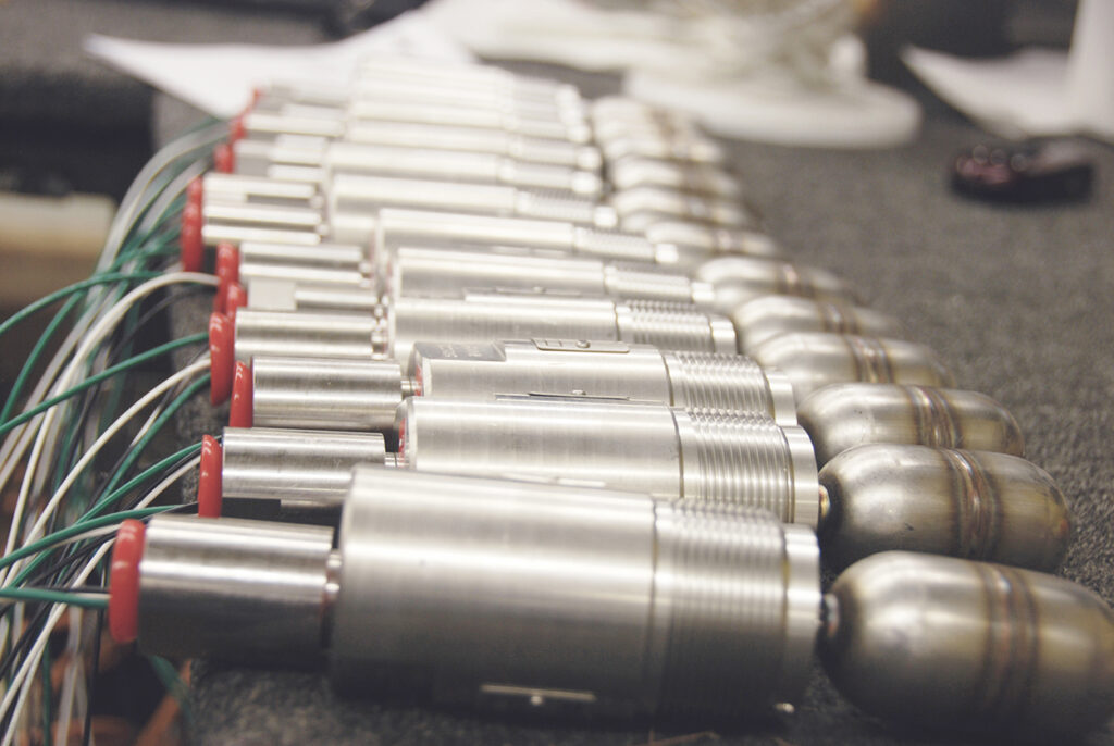
Level Switches
SOR offers Level Switches using different technologies to handle the diversity of applications. Float and Displacer-operated level switches are considered mechanical devices because of their moving parts, the buoyancy principle of operation, and because they don’t require a power supply. RF and Ultrasonic level switches are referred to as electronic products as they require a power supply, have no moving sensor parts, and work on the principles of capacitance and sound transmission.
Learn more on Float Operated Level Switch Operation and Displacer Operated Level Switch Operation.
SOR recognizes that there is no industry convention with respect to terminology and definitions pertinent to level switches. This glossary applies to SOR Level Switches.
Admittance – The measure of the ability of current to flow through an electrical circuit.
Adjustable Differential – Also known as ‘adjustable dead band’ – The ability to precisely set the actuation and deactuation points of a switching element or relay.
Attraction Sleeve – A magnetic component that travels with the stem movement and actuates/deactivates a magnetically coupled switch mechanism with changing liquid levels.
Capacitance – The ability of a device to store an electrical charge.
Capacitor – A component that stores an electrical charge; it consists of two conductive surfaces separated by an insulator (dielectric).
Chamber – A metal externally mounted vessel that contains the liquid level sensing components and exposes them to the same liquid levels as a main process vessel.
Continuous Level Measurement –Indicating level changes over a varied distance or height.
Dielectric Constant – A measure of the non-conductivity of an insulating material
Differential – The difference in level between the actuation and deactivation points; also referred to as hysteresis, reset value, or dead band.
Displacer Operated – The sensor is a weight (displacer) heavier than the liquid, which is suspended by a spring. When liquid contacts the displacer, a buoyant force is produced, which causes the spring to retract slightly to a new equilibrium position. When the spring retracts the attraction sleeve moves upward into the field of the external magnet, actuating the switch.
DPDT Switching Element – Double-Pole, Double-Throw (DPDT) is two SPDT elements operated by a common lever assembly so simultaneous actuation/deactuation occurs at both increasing and decreasing level set points. If desired, two independent circuits can be switched.
Dry Heat – Heat that transfers from the process through direct conduction, only where it contacts the enclosure.
Dual-Stage – A level instrument that detects two discrete level points.
Enclosing Tube – A protective tube that allows the attraction sleeve to engage the magnetic field of the switching element while keeping the switch isolated from the process media.
Failsafe – Refers to the safe mode of operation upon failure or loss of power to an instrument. A de-energized relay will have continuity between the Normally Closed and Common terminals.
Float-Operated – A float rides on the process liquid surface, precisely tracking liquid surface motion. Rising liquid level lifts the float, moving the attraction sleeve upward into the field of the external magnet, actuating the switch.
Hazardous Area – Refers to an area containing a mixture of flammable liquids, gasses, or dusts capable of ignition in the presence of an electrical spark.
Hermetically Sealed – The method of factory sealing an electrical switching element so that it is unaffected by ambient conditions. The enclosure is completely sealed from the environment using techniques such as welding, soldering, brazing or glass-to-metal fusion.
Integral – Term for mounting a level instrument directly into the primary process vessel (no external chamber).
Level Instrument – A device that senses a level change in a process media and provides an indication of position.
Level Switch – A device that senses a change in process level and then actuates a switching mechanism or relay when a pre-determined level set point is reached.
Line Power – Sometimes referred to as ‘four-wire’ – where the power supply and the output signal is transmitted on different pairs of wires.
Loop Power – Commonly referred to as ‘two-wire’ – where the power supply and output signal is transmitted on the same pair of wires.
Manual Check – A method of actuating a switch mechanism or relay to verify functionality without physically changing the liquid level in the vessel.
Normally Closed Contact – The electrical contact of a switching element or relay that current can flow through when in the non-actuated, ‘shelf position’.
Normally Open Contact – The electrical contact of a switching element or relay that current cannot flow through when in the non-actuated, ‘shelf position’.
Point Control – Level indication at a specific point.
Reset Point – The level at which the switching element returns to its normal operating position (deactuates after actuating).
Remote – A type of instrument where a portion of the unit is some distance from the process vessel, usually electronics mounted separately from the sensor in the process.
Sealed Chamber – A welded vessel assembly where the internal sensor components cannot be accessed for maintenance or repair.
Serviceable Chamber – A vessel that can be opened for sensor component maintenance or repair, usually through flanged connections.
Set Point – The measured level height at which a switching element or relay actuates, typically expressed as an increasing or decreasing level.
Single-Stage – A level instrument that detects only one discrete level point.
SPDT Switching Element – Single Pole, Double Throw elements have three electrical connections; C = Common, NO = Normally Open, NC = Normally Closed.
Specific Gravity – The ratio of the density of a liquid to the density of water.
Steam Heat – Heat that is carried with the vapor from the process to every internal portion of the enclosure.
Tandem Floats – Utilization of two independent floats in a level instrument to actuate two independent switch mechanisms.
Temperature Extension – Components designed to reposition the electrical switch elements or relays away from damaging process temperatures.
Time Delay – A method or device to delay the actuation of a switch or relay after the sensor’s initial detection of level change; can be used to minimize the effect of process turbulence.
Trim – The float or displacer, attraction sleeve, and other related parts that make up the sensor in a mechanical level switch. These components are exposed to the process liquids and vapors.
Triple-Stage – A level instrument that detects three discrete level points
Wetted Parts – Components of the instrument that come in contact with the liquid or gas process media.
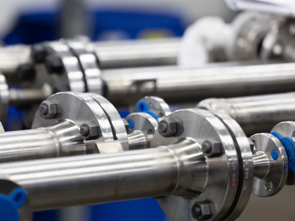
Magnetic Level Indicators
SOR Magnetic Level Indicators offer clear and reliable visual indications of most any process liquid level. Designed to work in a wide variety of process conditions, SOR Magnetic Level Indicators are perfect for industries such as Oil and Gas, Refining, Power Generation, Petrochemicals, and more. SOR recognizes that there is no industry convention with respect to terminology and definitions pertinent to Magnetic Level Indicators. This glossary applies to SOR Magnetic Level Indicators. Learn more about the 1100 Series Magnetic Level Indicator and the vista™ indicator.
Bridle – A bridle is a secondary chamber attached to the main chamber of the Magnetic Level Indicator (MLI). This secondary chamber can be used to accommodate other technologies such as Guided Wave Radar (GWR) and switches.
Center to Center – The center-to-center dimension is the distance between the middle of the top process connection and the middle of the bottom process connection.
Chamber – The chamber consists of piping and connections that are welded together to be connected to a vessel. Process liquid enters the MLI chamber through the process connections and rises at the same rate and level as the primary chamber.
Electrical Heat Trace – Electrical heating elements are run along the lining of the chamber to ensure the process material stays at the same temperature due to colder outside temperatures.
Flashing and Boiling Protection – A spring is placed at the top of the chamber to lower the impact of the float in the case of pressure build-up from flashing and boiling. Also, guide rods are placed inside the chamber to allow the flashing gasses to pass by the float.
Float – The float rides on top of the liquid in the chamber at the same rate as the fluid. Magnets inside of the float interact with the indicator on the outside of the chamber.
Indicator – The indicator consists of magnetically coupled flags. As the float inside of the chamber rises, the magnet turns the flags to indicate the liquid level.
Steam Heat Trace – Steam heating tubes are run along the lining of the chamber to ensure the process material stays at the same temperature due to colder outside temperatures.
Vent and Drain Connections – A vent connection is placed at the top of the chamber to vent off pressure in the chamber. A drain connection is placed at the bottom of the chamber to drain off liquid left in the chamber below the bottom process connection.
Viewing Angle – The viewing angle is the angle at which the level indication is still visible.
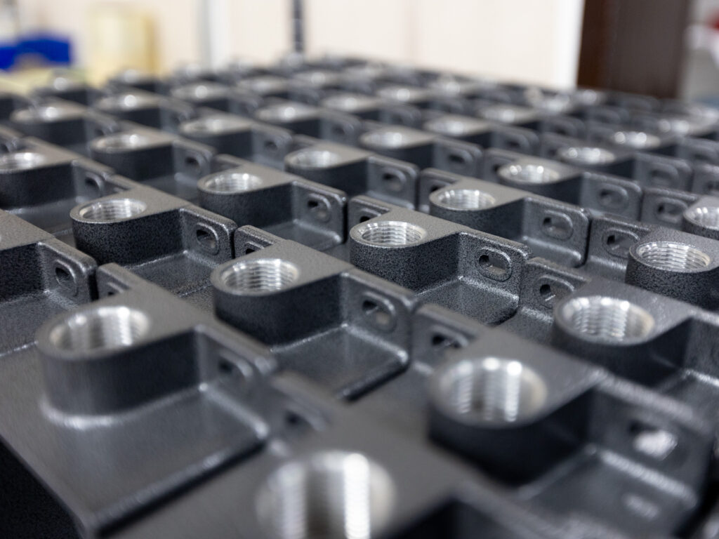
Pressure Switches
The pressure sensing element of the SOR Pressure Switch is a force-balanced, piston-actuated assembly. The sensing element is sealed by a flexible diaphragm and a static o-ring (the o-ring is eliminated on welded diaphragm systems). Media pressure on the area of the piston counteracts the force of a range spring (adjustable by an adjusting nut) which moves the piston shaft only a few thousandths of an inch to directly actuate the electrical snap-action switching element. This principle of operation virtually eliminates friction and resultant wear.
Learn more about Pressure Switch Operating Principles
SOR recognizes that there is no industry convention with respect to terminology and definitions pertinent to pressure switches. This glossary applies to SOR Pressure Switches.
Absolute pressure – Pressure measured against a reference of full vacuum. Absolute pressure is normally referred to as PSIA.
Adjustable range – The span of pressure between upper and lower limits within which the pressure switch may be adjusted to actuate/deactuate.
Dead band – The difference in pressure between the increasing set point and the decreasing set point. Also known as differential, hysteresis, reset value, and reset.
Differential – The difference between two sensed pressures.
DPDT switching element – Attained using two synchronized SPDT switching elements which actuate together at increasing set point and deactuate together at decreasing set point. Discrete SPDT switching elements allow two independent circuits to be switched; i.e., one AC and one DC.
Firesafe – The ability of a welded seal pressure sensor to contain the process at elevated temperatures up to 1900°F at the rated overrange pressure, unsupported by the body of the pressure switch.
Gauge pressure – Pressure measured against atmospheric pressure. It is the pressure sensed above ambient pressure.
Hermetically sealed – The method of sealing an electrical switching element so that it is unaffected by ambient surroundings. The enclosure is completely sealed from the environment using fusion techniques such as welding, soldering, brazing, or glass-to-metal fusion.
Overrange – The maximum input pressure that may be continuously applied to the pressure switch without causing a permanent change of set point, leakage, or material failure.
Pressure switch – A bi-stable electromechanical device that actuates/deactuates one or more electrical switching element(s) at a predetermined discrete pressure/vacuum (set point) upon rising or falling pressure/vacuum.
Process – Liquid or gas that is being sensed by a pressure switch. Also known as “process media”.
Proof pressure – The maximum input pressure that may be continuously applied to the pressure switch without causing leakage or catastrophic material failure.
Repeatability – The ability of a pressure switch to successively operate at a set point that is approached from a starting point in the same direction and returns to the starting point over three consecutive cycles to establish a pressure profile.
Repeatability on SOR switches will be smaller than 1% of full scale per ISA/ANSI S51.1.
Reset point – The pressure value at which the switching element changes state. It is normally expressed in a unit of measurement and as increasing or decreasing.
Set point – That discrete pressure at which the pressure switch is adjusted to actuate/deactuate on rising or falling pressure. It falls within the adjustable range and the set point value is usually called out as increasing or decreasing pressure.
SPDT switching element – Single-Pole, Double Throw (SPDT) has three connections: C — Common, NO — Normally Open, and NC — Normally Closed, which allows the switching element to be electrically connected to the circuit in either NO or NC state.
Vacuum – Pressure measured that is less than atmospheric pressure.
Wetted parts – Components of a pressure sensor that are exposed to the process media.
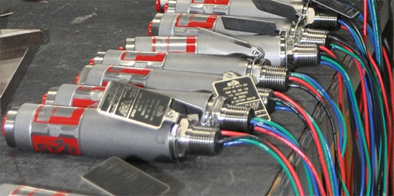
Pressure Transmitters
SOR Pressure Transmitters are durable and compact devices. They provide continuous pressure measurement and some models also provide a switch output. SOR Pressure Transmitters utilize a diaphragm-sensor design where a Wheatstone bridge circuit, containing two variable resistors, is placed on the diaphragm of the sensor. As pressure is applied to the sensor, the resistance of the variable resistors changes and a corresponding voltage difference in the circuit is monitored. The Pressure Transmitter can use this change in voltage to measure and record a change in pressure.
SOR recognizes that there is no industry convention with respect to terminology and definitions pertinent to Pressure Transmitters. This glossary applies to SOR Pressure Transmitters.
1-5V Output – A configuration of the Pressure Transmitter where the pressure range sensed is linearly translated to an electrical signal output that ranges from 1 to 5 volts. (This output provides low current consumption and therefore less power consumption.)
4-20mA Output – A configuration of the Pressure Transmitter where the pressure range sensed is linearly translated to an electrical signal output that ranges from 4 to 20 milliamps. (Unlike the 1-5V output, this output is not vulnerable to signal loss over long distances.)
Absolute Pressure (psia) – The sum of gauge pressure (psig) and atmospheric pressure (14.7 psi, 1.01 bar).
Adjustable Range – The span of pressure between upper and lower limits within which the Pressure Transmitter may provide continuous monitoring and solid state switch actuation/deactuation.
Ambient Temperature – The temperature of a Pressure Transmitter’s internal electronics.
Best Fit Straight Line (BFSL) – A straight line drawn exactly through the center of a group of data points.
Burst Pressure – The pressure at which mechanical failure and loss of pressure containment within the transmitter will occur.
Compensated Temperature Range – The range of temperatures that a Pressure Transmitter’s accuracy has been tested over. (If used outside of this range the accuracy of the transmitter is no longer valid.)
Continuous Output – The constant sensing, translating, and transmitting of pressures by the pressure transmitter.
Continuous Output Accuracy – Defines the maximum possible deviation of a transmitter’s output from the perfectly measured value. (Sometimes defined as a percentage of the upper range limit, i.e. “0.10% URL”, so if the upper range limit is 100 psi then the value of the output could vary from the actual input by up to 0.1 psi.)
Dead Band – The pressure range, centered on the set point, through which an input can be varied without initiating an observable response, usually defined as a percentage of the span. (Also known as hysteresis, differential, reset value, and reset.)
Diaphragm Seal – A flexible barrier used to protect the Pressure Transmitter’s sensor and keep it isolated from the process.
Differential Pressure (psid) – The difference in pressure between two separate points in a system.
Differential Pressure Transmitter – A Pressure Transmitter with the capability of measuring differential pressure.
Digital Compensation – A function of the transmitter where it collects inputs over a specific time interval and outputs the average of those inputs. This function can be used to eliminate the transmitter’s reaction to rapid changes in pressure. (Also known as damping.)
Dual Seal – A combination of a primary seal and a secondary seal that require the failure of two independent seals in order for the process fluid to leak out of the isolated process connection port.
EMC Protection – The prevention of both emission and reception of electromagnetic waves through the transmitter’s housing.
Explosion Proof (Flame Proof) – A device that is able to contain an internal explosion without letting the explosion escape into the atmosphere.
Fail-safe State – the state that the Pressure Transmitter’s switch output reverts to if power is removed from the transmitter; either open or closed. (For the 800 series the fail-safe state is always open.)
Full-Scale Pressure Range (FSPR) – The maximum pressure range that a Pressure Transmitter is designed to measure.
Gauge Pressure (psig) – Pressure measured against atmospheric pressure.
HART – Highway Addressable Remote Transducer (HART) is a digital communications protocol used to read and configure a Pressure Transmitter’s output.
Hermetically Sealed – The method of sealing an electrical switching element so that it is unaffected by ambient surroundings. The enclosure is completely sealed from the environment using fusion techniques such as welding, soldering, brazing, or glass-to-metal fusion.
Hydrostatic Pressure – The pressure produced by the weight of a resting liquid above the measurement location.
Ingress Protection (IP) Rating – A classification of the level of protection that a device’s body provides against the intrusion of objects, dust, and water.
Intrinsically Safe – A term used for devices that don’t generate or consume enough power to cause combustion.
Long-Term Stability – The amount of change in a device’s measurement under the exact same conditions, over a period of time.
Loop Powered – A device that is powered by the 4-20 mA current from a power supply that is connected in series with the device.
Loop Resistance – The total resistance that the device causes within the power supply loop.
Modbus RTU Serial Communications – A communication protocol by Modicon systems that provides the capability to read and configure a Pressure Transmitter’s output.
Normally Closed – A switch preset where the switch is closed until the set point is reached and then it opens.
Normally Open – A switch preset where the switch is open until the set point is reached and then it closes.
Over Pressure – The maximum pressure that a device can withstand before the performance of the device is affected.
Pressure Transducer – A device that senses pressure and translates it into an output voltage signal.
Pressure Transmitter – A device that senses pressure and translates it into a 4-20 mA output signal.
Process Temperature – The temperature of the process media that the transmitter is monitoring.
Repeatability – The amount of change that a device’s output experiences at the same measurement point, over a specific number of cycles through the device’s measurement range.
Response Time – The amount of time that a device’s output takes to reflect a change in the pressure being measured.
Set Point – The specific pressure at which the Pressure Transmitter’s switch output is configured to actuate/deactuate on the rising or falling pressure.
Solid State Switch Output – An electronic switching function that switches on or off when a small voltage is applied to its terminals. (This voltage is applied to the solid state switch when the transmitter senses that the pressure has reached the set point.)
Span – The difference between the lowest point and the highest point in a configured measurement range. (For example, if a 250 psi transmitter is adjusted to measure a range of 50 psi to 200 psi, then the span is 150 psi.)
Static Line Pressure – The total pressure at a specific point within a pressurized pipe.
Switch Output Accuracy – The maximum possible deviation of the Pressure Transmitter’s switching pressure to the perfectly measured pressure. (Sometimes defined as a percentage of the upper range limit, i.e. “0.25% URL”, so if the upper range limit is 100 psi then the transmitter’s switching pressure could vary from the actual pressure by up to 0.25 psi.)
Turndown Ratio – The ratio between the highest and lowest possible span settings for a transmitter. (For example, if a 1,000 psi transmitter has a turndown ratio of 5:1, then the highest possible span is 0 to 1,000 psi and the lowest possible span is 0 to 200 psi.)
Upper Range Limit (URL) – The highest value that the transmitter can possibly measure.
Vacuum – Pressures that are less than atmospheric pressure.
Wetted Materials – The materials that are exposed to the process media.
Zero – The lowest value that a Pressure Transmitter is currently configured to measure.
Sampling Systems
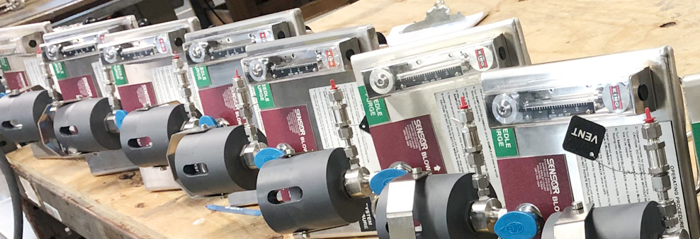
SENSOR Sampling Systems provides a representative sample that is safe for both the operator and the environment. Our systems are designed to meet Leak Detection Repair (LDAR), Maximum Achievable Control Standards (MACT), and Volatile Organic Compounds (VOC) emission standards.
EPA Regulations mandate the use of environmentally safe, closed loop and closed vent sampling systems. Our systems meet these strict EPA requirements while providing a safe, reliable method for collecting representative samples in a manner that minimizes exposure to the operator and the environment. SENSOR sampling is dedicated to providing a simple way to collect a repetitive, quality sample, reduce emissions and create safe conditions in which to work. We offer many different types of systems specifically designed to meet your exact requirements.
Learn more about how the Liquefied Gas Sampling System (LGSS) and the Vapor Gas Sampling Systems (VSS) work.
SOR recognizes that there is no industry convention with respect to terminology and definitions pertinent to sampling systems. This glossary applies to SOR Sampling Systems.
Asphalt – A dark brown-to-black cement-like material obtained by petroleum processing and containing bitumens as the predominant component; used primarily for road construction. It includes crude asphalt as well as the following finished products: cement, fluxes, the asphalt content of emulsions (exclusive of water), and petroleum distillates blended with asphalt to make cutback asphalts. Note: The conversion factor for asphalt is 5.5 barrels per short ton.
Benzene (C6H6) – An aromatic hydrocarbon present in small proportion in some crude oils and made commercially from petroleum by the catalytic reforming of naphthenes in petroleum naphtha. Benzene is made from coal in the manufacture of coke. Used as a solvent in the manufacture of detergents, synthetic fibers, petrochemicals, and as a component of high-octane gasoline.
Block Valve – Any valve used to isolate the Sampling System panel from the active process line.
Closed-Loop Sampling – A methodology for extracting process samples from an active process line without allowing the release of fugitive emissions.
CRN – Canadian Registration Number. A number issued by each province or territory of Canada to the design of a boiler, pressure vessel, or fitting. The CRN identifies the design has been accepted and registered for use in that province or territory.
Dead Volume – Any volume of process media that is not actively circulating within the process piping. Considered “non-representative” of the current process conditions.
Dual Phase Sampling – designed for the collection of Liquid and/or Gas samples during the Hydro-cracking and Hydro-treating process.
Eductor – A jet-type pump that does not require any moving parts to be able to pump out a liquid or gas from a certain area. These pumps make use of their structure to transfer energy from one fluid to another via the Venturi effect.
Emissions – Anthropogenic releases of gases into the atmosphere. In the context of global climate change, they consist of radiatively important greenhouse gases (e.g., the release of carbon dioxide during fuel combustion).
Fast Loop – A circuit or loop of tubing flowing from the process line to a certain point in a sampling system and then back to the process line. It ensures that the sample arriving at a certain point in the sample system is timely and fresh.
Fixed Volume – A pre-determined volume that is reliably and repeatedly dispensed by the Sampling System. The system is designed to dispense this exact volume with each sampling operation.
Flare – A tall stack equipped with burners used as a safety device at wellheads, refining facilities, gas processing plants, and chemical plants. Flares are used for the combustion and disposal of combustible gases. The gases are piped to a remote, usually elevated, location and burned in an open flame in the open air using a specially designed burner tip, auxiliary fuel, and steam or air. Combustible gases are flared most often due to emergency relief, overpressure, process upsets, startups, shutdowns, and other operational safety reasons. Natural gas that is uneconomical for sale is also flared. Often natural gas is flared as a result of the unavailability of a method for transporting such gas to markets.
Flowmeter – A component that measures the flow rate of liquids and gases through a process system.
Heating Equipment – Any equipment designed and/or specifically used for heating ambient air in an enclosed space. Common types of heating equipment include: central warm air furnaces, heat pumps, plug-in or built-in room heaters, boilers for steam or hot water heating system, heating stoves, and fireplaces.
Hydrocarbon Gas Liquids (HGL) – A group of hydrocarbons including ethane, propane, normal butane, isobutene, and natural gasoline, and their associated olefins, including ethylene, propylene, butylene, and isobutylene. As marketed products, HGL represents all natural gas liquids (NGL) and olefins. EIA reports the production of HGL from refineries (liquefied refinery gas, or LRG) and natural gas plants (natural gas plant liquids, or NGPL).
Hydrogen Sulfide (H2S) – a colorless gas with the characteristic foul odor of rotten eggs; it is heavier than air, very poisonous, corrosive, flammable, and explosive; properties shared with the denser hydrogen chalcogenides.
Isolation Valve – See Block Valve (NOTE: This may sometimes refer to a secondary panel-mounted valve in Fixed Volume systems)
Liquefied Petroleum Gases (LPG) – A group of hydrocarbon gases, primarily propane, normal butane, and isobutene, derived from crude oil refining or natural gas processing. These gases may be marketed individually or mixed. They can be liquefied through pressurization (without requiring cryogenic refrigeration) for convenience of transportation or storage. Excludes ethane and olefins. Note: In some EIA publications, LPG includes ethane and marketed refinery olefin streams, in accordance with definitions used prior to January 2014.
LPG – Liquefied Petroleum Gas
Needle Purge – The ability to expel any remaining process media from the process needle into the Sample container, thus eliminating the possibility of plugging or cross-contamination of samples.
Outage tube – A “cut to length” tube placed inside of the sample cylinder used as a way to remove the excess sample from the cylinder via manual evacuation after the sample cylinder assembly is removed from the sampler.
Pressure – Force per unit area, commonly expressed in pounds per square inch (PSI) or bar.
Process Line – A large pipe in a plant that moves the liquid or gas product from one step or process to another.
Process Needle – Needle through which a liquid process sample is dispensed into a bottle.
Reid Vapor Pressure (RVP) – An indirect measure of the rate at which petroleum liquids evaporate. It’s the absolute vapor pressure of a crude oil, or of single or mixed liquid petroleum products, as measured by the Reid Method (ASTM Method D 323).
Representative Sample – A process sample that is identical to the process media actively circulating in the process piping, and representative of current process conditions.
Sample Bomb – See Sample Cylinder
Sample Cylinder – A sample container designed to capture and safely transport liquid or gas (vapor) samples under high pressure.
Sampling System – A system that is employed in many industries that draws a sample from a process line and prepares it for analysis in an analyzer.
Sampling Valve – Main valve which controls the dispensing of a process sample.
Septum – Teflon-coated, rubber diaphragm through which the process and vent needles access the sample bottle.
Sight Glass – A transparent tube or window through which the level of liquid in a reservoir or supply line can be checked visually.
Sulfinert – A flexible silicon coating that makes flow paths inert for better process control, consistent sampling, and analytical results.
Tube Fitting – A leak-tight mechanical connection between two pieces of tubing (or tubing and a component) that may be assembled with simple tools and reassembled numerous times.
Vapor Pressure – The pressure exerted by a vapor in thermodynamic equilibrium with its condensed phases (solid or liquid) at a given temperature in a closed system. The equilibrium vapor pressure is an indication of a liquid’s evaporation rate. It relates to the tendency of particles to escape from the liquid (or a solid). A substance with high vapor pressure at normal temperatures is often referred to as volatile.
Vent Needle – Needle through which vapors are evacuated from a sample bottle.
Volatile Organic Compounds (VOCs) – Organic compounds that participate in atmospheric photochemical reactions.
Temperature Sensors
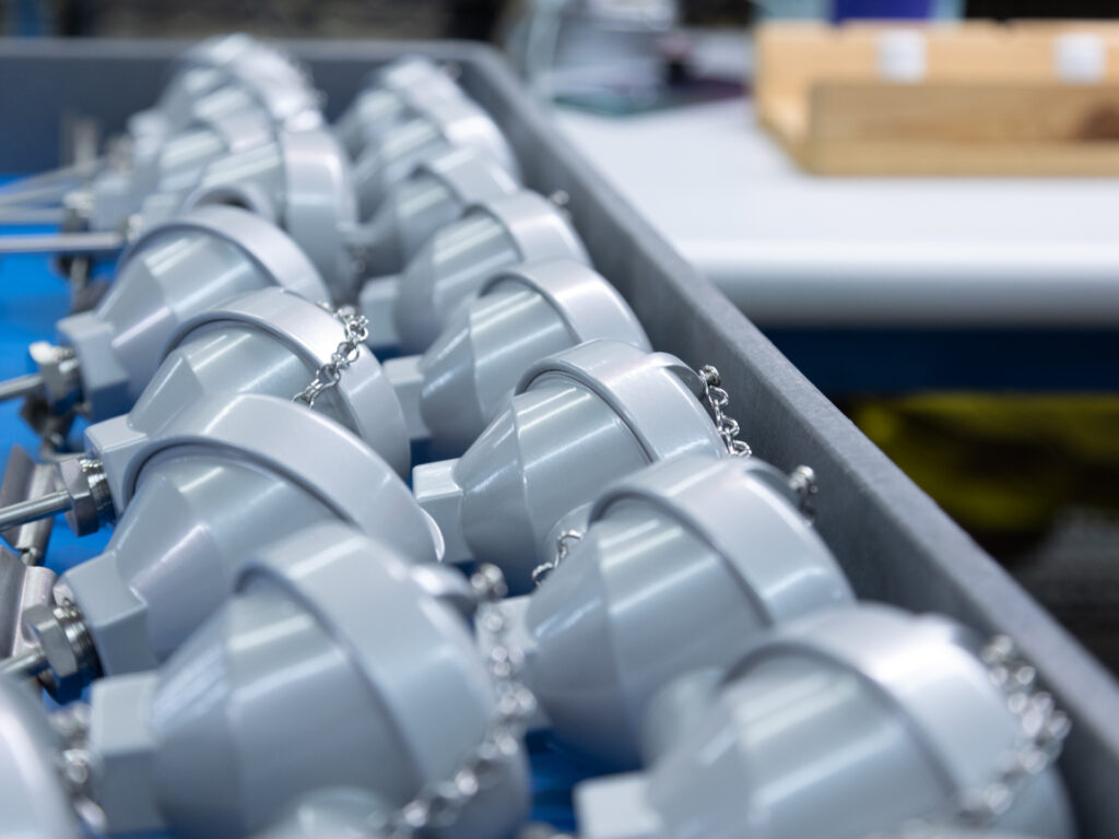
The SOR Temperature Assemblies can be an RTD (Resistance Temperature Detector) or Thermocouple as the primary temperature sensing device. They can also be supplied with a Thermowell that protects the Temperature element from the process and allows for removal without shutting down and draining the pipe or vessel for replacement. RTDs provide a resistance output that can be packaged with a Temperature transmitter that converts the resistance input into a 4-20 mA or other industry-standard digital output. A Thermocouple generates an mV output as temperature changes and can also be supplied with a Temperature Transmitter.
SOR recognizes that there is no industry convention with respect to terminology and definitions pertinent to temperature sensors. This glossary applies to SOR Temperature Sensors.
The following are some common industry terms and reference standards for RTDs and Thermocouples.
Lagging Length – Additional length of Bar stock on the back side of the Thermowell for the instrument connection. Industry standards are to add the lagging length to the base length of the Head stock of the well. For threaded wells this is usually 1.75”, and for flanged wells it is 2.25”. The lag extends the instrument connection to get through piping insulation or heat considerations for the connection head typically at the end of the temperature assembly.
RTD – Utilize the basic characteristic that the Electrical Resistance of Metals increases with temperature. The resistance value is measured electronically using the voltage generated across the element by an electrical current (about 1 milliamp).
RTD Accuracy – The industry has standardized two types of accuracy for Platinum 100 ohm RTD Elements. They are Class B (+/- 0.8oC at 100oC), the industry standard, and the higher accuracy Class A (+/- 0.35oC @ 100oC). Other elements for even higher accuracy are available upon request.
Repeatability – Defined as the ability to repeat the same output value at a given temperature point in a spanned temperature range. Depending on the process conditions, RTDs typically are repeatable to +.14o or .05%, whichever is greater.
Response Time – Measured as the time necessary for a sensor to report a 63.3% step change in temperature in water moving transverse to the sensor sheath at 3 fps.
Thermocouple – Two dissimilar metals that are joined together, if the temperature at each end of the wire is different, a current will flow, known as EMF (Electro Motive Force).
Thermocouple Accuracy – The Industry has published accuracy specs for the different Thermocouple Calibrations – Type J, K, T, N, and the Nobel Calibrations (Platinum) R, S & B. Typical Industrial grade accuracy is +/- 2.2oC or 0.75% of reading whichever is greater. Higher purity T/Cs – call special limits are specified in the +/- 1.1oC or 0.4% of reading
Thermowell – A pressure-tight receptacle that protects and extends the life of a temperature sensor in processing applications where the sensor is not mechanically or chemically compatible with the process environment. Also allows for the installation and removal of the temperature element without shutting down the process of replacement.
Stability – Defined as the ability of a sensor to maintain its stated accuracy over an extended period of time, usually one year, at its rated temperature. RTDs when used properly maintain stability much greater than thermocouples.
U length – Length of the Stem of the thermowell – as measured from the bottom (Tip) to the flange face or start of the process Threads/Head on Screw Wells.
Temperature Switches
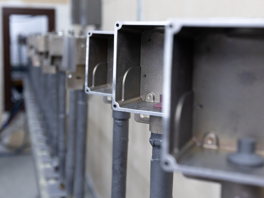
The SOR Temperature Switch utilizes a vapor-pressure thermal system. Fluid vapor pressure changes according to the influence of temperature on the sensing bulb. Process temperature changes cause proportional vapor pressure changes in the temperature sensing bulb that act on the diaphragm/piston assembly to actuate and deactuate a snap-action electrical switching element at discrete process temperatures. The instrument’s behavior is determined by the vapor pressure principle.
SOR recognizes that there is no industry convention with respect to terminology and definitions pertinent to temperature switches. This glossary applies to SOR Temperature Switches.
Adjustable Range – The span of temperature between upper and lower limits within which the temperature switch can be adjusted to actuate/deactuates.
Capillary – Small diameter tubing used to transfer the measured vapor pressure in the temperature bulb to the piston sensor on remote mount units.
Dead Band – The difference in temperature between the increasing set point and decreasing set point. Also known as hysteresis, or reset.
Direct Mount – Describes the style of the temperature switch where the temperature bulb and switch housing assembly are closely coupled when installed in the process line or vessel.
DPDT Switching Element – DPDT is achieved using synchronized SPDT switching elements that actuate together at increasing temperature set point and deactuate together at decreasing set point. Discrete SPDT switching elements allow two independent circuits to be switched.
Hermetically Sealed – A welded steel capsule with glass-to-metal, factory-sealed electrical leads that isolates the electrical switching element(s) from the environment.
Maximum Process Pressure – The maximum process pressure to which the temperature sensing bulb can be exposed without being protected by a thermowell.
Overrange – Overrange temperature is the temperature to which the sensing bulb can be continuously exposed without causing a permanent change of set point or distortion sufficient to cause leakage or significant degradation of the fill fluid. Temperatures greater than overrange could cause permanent damage and render the device inoperative.
Remote Mount – Describes the style of the temperature switch where the temperature bulb and housing assembly are separated by distance and the vapor pressures from the temperature bulb are transferred to the piston sensor through a capillary tube.
Repeatability – The ability of a temperature switch to successively operate at a set point that is approached from a starting point in the same direction and returns to the starting point over consecutive cycles to establish a temperature profile. The closeness of the measured set point values is normally expressed as a percentage of full scale (maximum adjustable range temperature.)
Set Point – That discrete temperature at which the temperature switch is adjusted to actuate/deactuate on rising or falling temperature.
SPDT Switching Element – Single-Pole, Double-Throw (SPDT) has three connections: C-Common, NO-Normally Open, and NC-Normally Closed, which allows the switch to be electrically connected to the circuit in either NO or NC state.
Temperature Switch – A bi-stable electromechanical device that actuates/deactuates one or more electrical switching element(s) at a predetermined discrete temperature (set point) upon rising or falling temperature.
Thermowell – A tubular metal component that protects the temperature-sensing bulb from high pressures or corrosive processes.